First Report of Activities at
UPENN
"Understanding a Cryogenic
system, design of its individual
components,
and design and testing bolometers"
Daniel Ferrusca -- INAOE
Miguel Velazquez – INAOE
Advisor:
Dr. David Hughes
INAOE
Dr. Mark Devlin
UPENN
May 21st – July 21st
Main activities at UPENN Lab:
General understanding of a cryogenic system.
General Understanding of a Preamplifier stage for a cryogenic system
- Design and tests of different active filters, for the filter with gain stage.
- Design of instrumentation amplifier gain stage.
- Design of general power supplies for the preamplifier circuits.
- Design of power supplies for JFET connections.
- Design of power supplies for bolometer bias.
- Test of Preamplifier in breadboard.
- Soldering of circuits and components in a "Vector Board".
- Test of Preamplifier in Vector Board.
- Design and construction of Preamplifier metal box.and its connectors.
- Final test of Preamplifier in metal box.
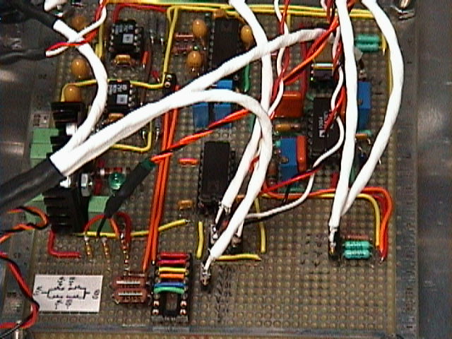
Figure 1, The components of the Preamplifier
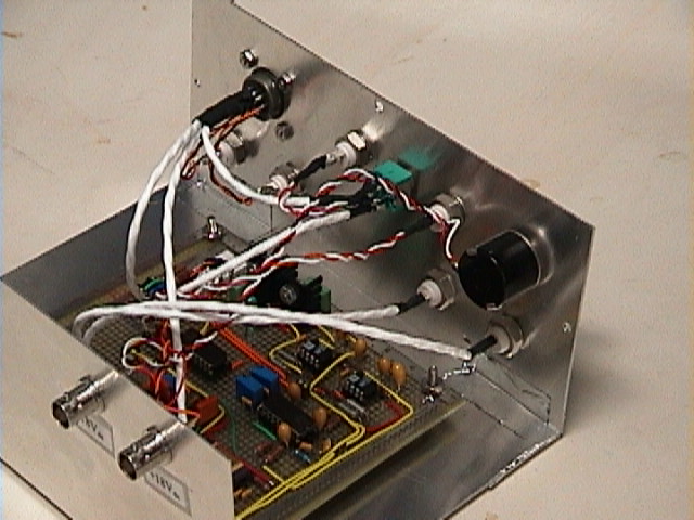
Figure 2 , Rear top view of the Preamplifier box
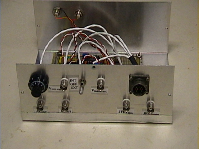
Figure 3, Front view of Preamplifier box
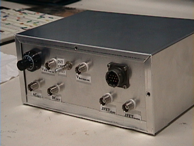
Figure 4, Completed box of preamplifier
Construction and assembly of JFET (Cu encapsulation).
- Calculation of length of G10 tube, for correct power dissipation.
- Calculation of length of manganin wires, for correct power dissipation.
- Put together G10 tube + JFET + socket, with STYCAST epoxy.
- Soldering of JFET, Manganin and socket connectors.
- Construction of copper can to encapsulate JFET.
- Soldering of copper can to JFET socket.
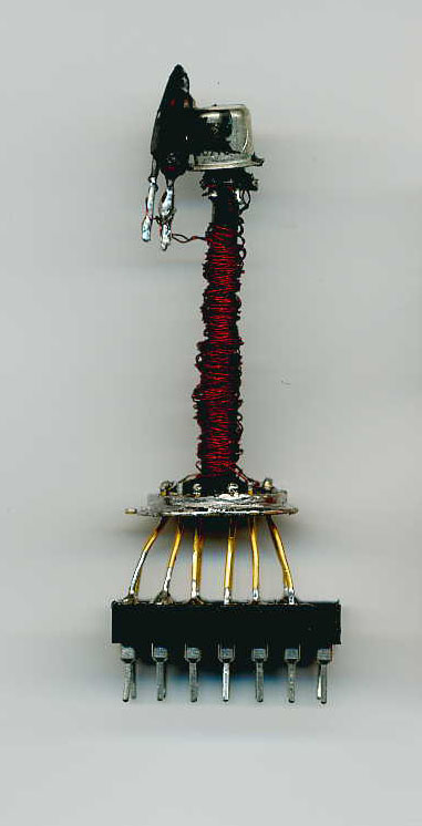
Figure 5, JFET connections
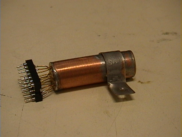
Figure 6, Final JFET Cu can
Design and construction of Cu-Al test table for cryostat base plate.
- Calculation of length of G10 four legs of table, for correct power dissipation.
- Put together, top of the table (copper) to bottom of table (aluminum) and four G10 legs. All this done with STYCAST epoxy.
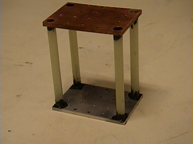
Figure 7, Test Cu-Al table for Cryostat
Design and construction of special purpose copper block to interface
outside connectors to inside sensor connectors.
- STYCAST connectors to copper block.
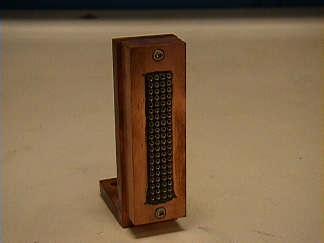
Figure 8, Cu block interface
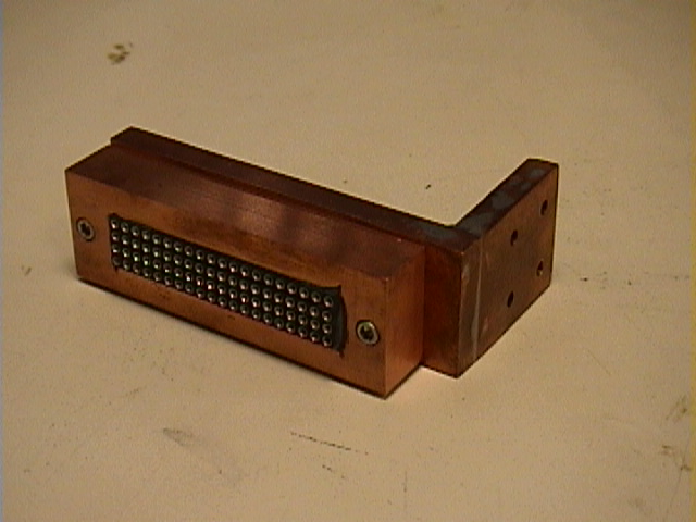
Figure 8, Cu block interface (another view)
Construction of outside connector of cryostat.
- Soldering of connector to special purpose piece of cryostat for connectors.
Soldering of manganin wires
to outside connector of cryostat. (this
wires will be connected to special purpose copper block interface for outside
connectors)
General Photos:
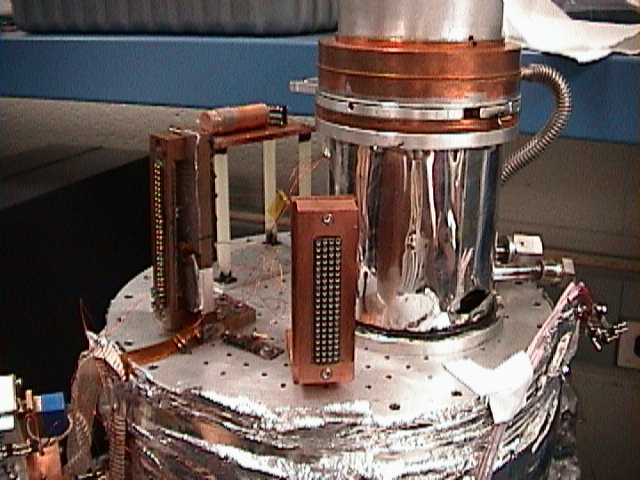
Figure 9, The cryostat, with our test table with JFET Cu can behind the fridge, and our Cu block interface at the front
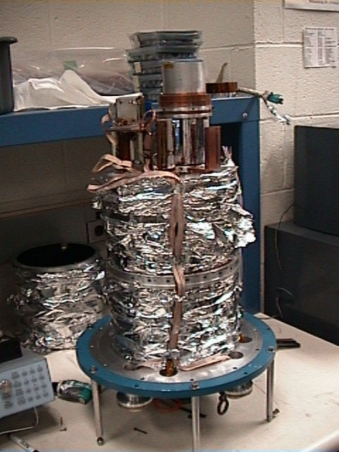
Figure 10, A view of the Cryostat, we are working with , now.
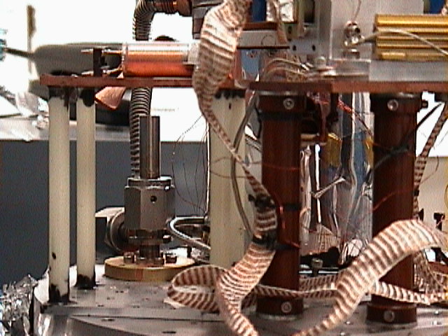
Figure 11, A close view of the base plate of the Cryostat
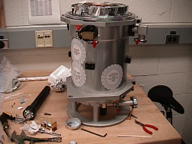
Figure 12, A
view of the Cryostat that came from
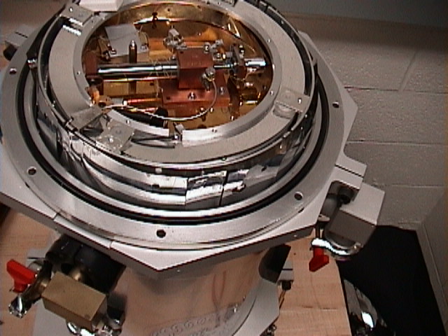
Figure 13, A
top view of the Cryostat that came from
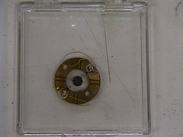
Figure 14, A bolometer of the UPenn Lab
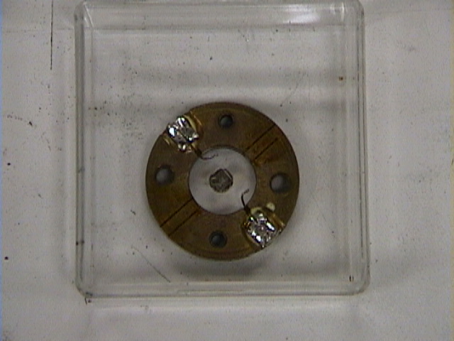
Figure 14, Another bolometer of the UPenn Lab
Some of the equipment we have bought:
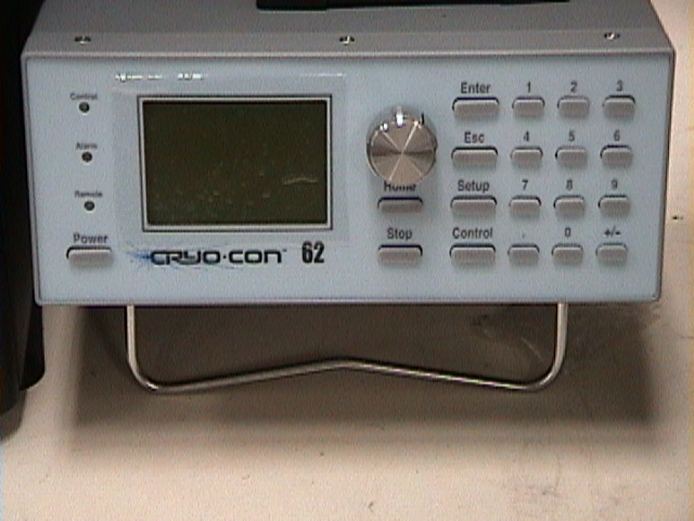
Figure 15, Temperature controller, to be used at temperatures as low as 100 mK
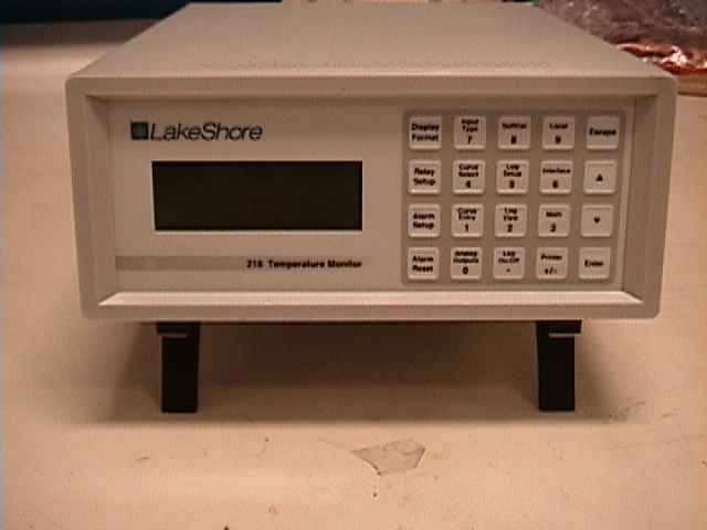
Figure 15, Temperature monitor
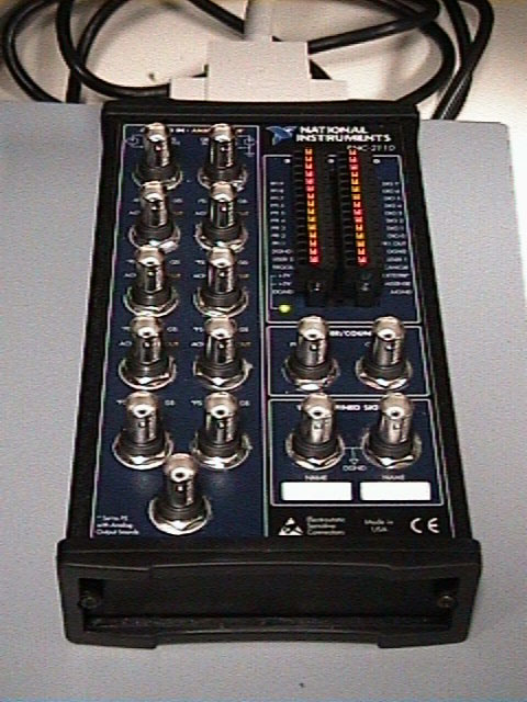
Figure 16, BNC connectors to connect IN/OUT signals to DAQ computer card (not shown)
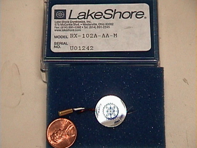
Figure 17, Ruthenium Oxide Temperature Sensor to be used from 0.05 K to 40 K
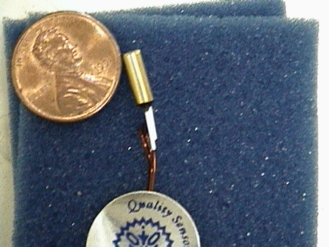
Figure 18, A close view of the Ruthenium Oxide Temperature Sensor
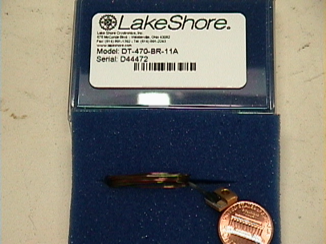
Figure 18, Silicon Diode Temperature Sensor to be used from 1.4 K to 475 K
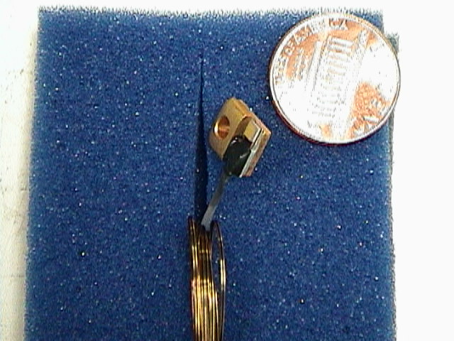
Figure 19, Close view of the Silicon Diode Temperature Sensor
Other activities include:
Calculations of Heat Capacity for different materials.
Connections of CRYCON Temperature Controller to PC computer.
Connections of LAKESHORE Temperature Monitor to PC computer.
Connections of DAQ board to PC.
Connections of GPIB board to PC
Intallation of LABVIEW software in Windows 2000.
Your students:

Figure 20, Daniel Ferrusca showing the parts made at Upenn Lab
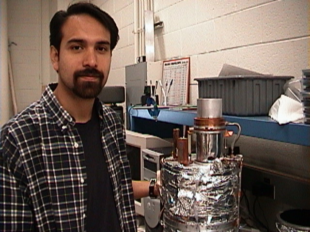
Figure 21, Miguel Velazquez with the cryostat